1969 Mustang Engine Information & Specs – 351 Cleveland V8 (5.8 L)

351 Cleveland V8 Technical Specs & Data

1968 Mustang 351 Cleveland V8

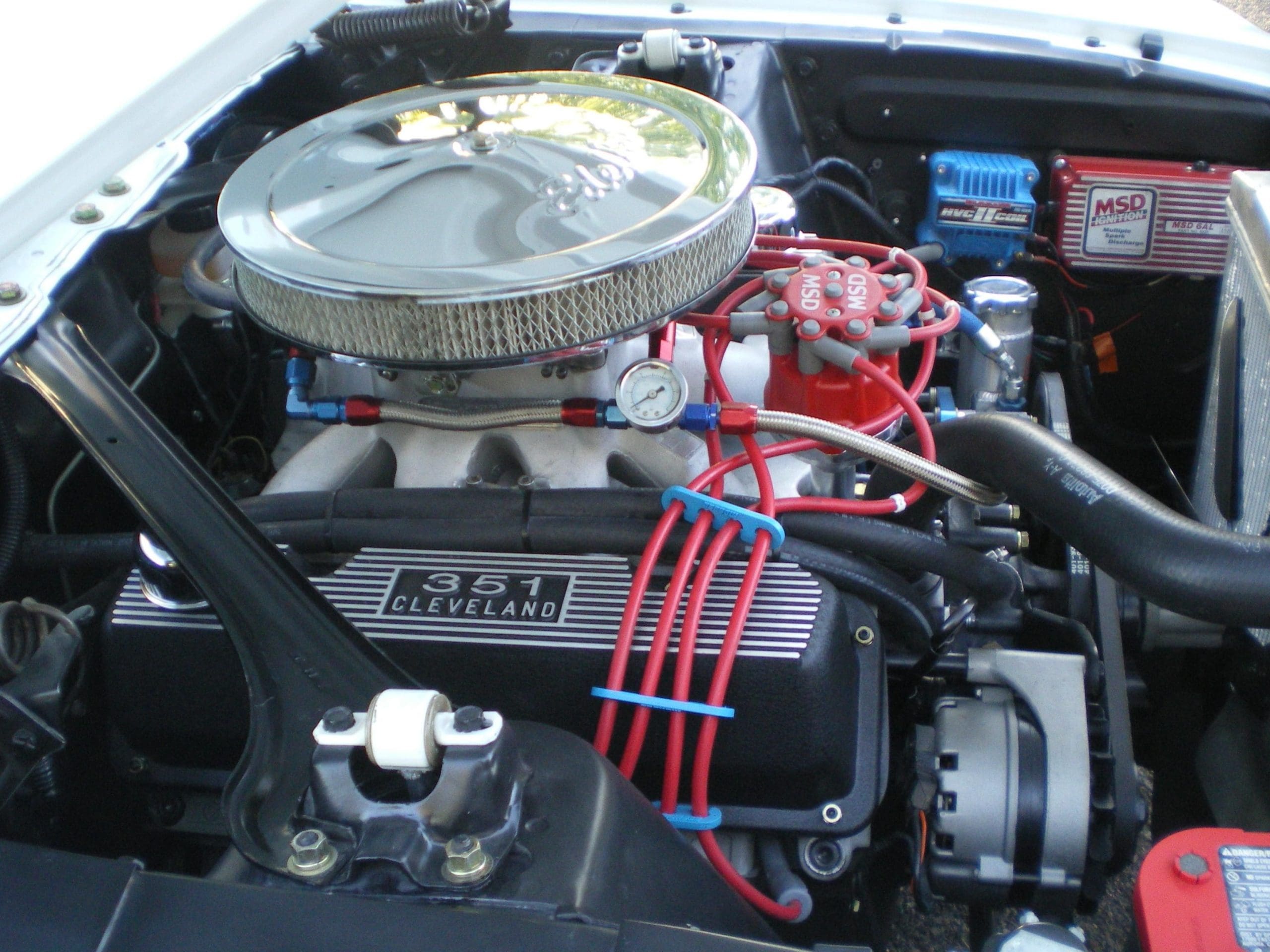
1969 Mustang Engine Information – 351 cubic inch V-8 (5.8 L Cleveland V8)

The 351 Cleveland Engine

The 351 Cleveland engine is one of the engines in the 335 FORD series of engines. Other engines in this series are the 351 Cleveland Boss, 351 Cleveland HO, 351 M and the 400 series.

The C behind the engine denotes the place of manufacture – Cleveland, Ohio. As opposed to a 351 W where the “W” stands for Windsor, Canada its birthplace. Now to clarify the “M” located behind some of the 400 series engines. It does not stand for ‘Modified” or “Michigan” as most people think. It is simply a suffix added to denote a different engine from the Cleveland and Windsor.

Some suffixes found on this engine family stand for performance options such as H.O. stands for High Output and CJ for Cobra jet. As a matter of fact, these engines were the result of Ford’s quest for a bullet proof medium displacement high performance engine for use in the production vehicles. Alas the timing was poor as the gas prices rose and the fickle public went on to grossly underpowered vehicles that moved at a pace between slow and slower.

The 351 Cleveland engines used “canted” valves and large intake and huge exhaust valves for maximum breath ability. A canted valve is set in the heads at an angle, not vertically. Canted valves increase performance by allowing the heads to flow a higher ratio of gas and exhaust in and out of the heads than normal valve design. As a result, power is increased and fuel efficiency is also increased. Because of these characteristics, 351 C engines are very well known in both the NASCAR and Pro Stock Drag car circles. When driven in everyday traffic, they can be fuel efficient operating as an engine would if it in the 300 CID size.

The 335 series engines use a dry manifold configuration. In other words, no coolant flows through the intake manifold. At the front of the block, there is an integral timing chain cover, at the top left hand side, coolant enters the block through the thermostat and then part of it goes through the radiator and part of it goes through the water pump. At this point below the thermostat on 351 C engines is a brass diverter valve. This diverter looks small and unimportant but it is critical. Made of brass it looks like a brass freeze plug with a hole in it and is driven into a seat below the thermostat. If you have an engine you are going to hot tank, REMOVE THE DIVERTER VALVE. Hot tanking will eat the brass and no one makes these that I can find. Your engine will overheat without this valve. To remove the piece, you can generally pry it up from a small hole located below it. Or you can sometimes drill a small 1/8 inch hole off to one side and remove it with a slide hammer puller. Do not destroy this piece. If you feel lucky go to your Ford dealer and ask for part # D0AZ – 8K517-A.

351 C 4 barrel engines produced through 1971 and all 351 C 2 bbl. engines use 2 bolt mains. All HO, Boss, CJ and 1972 – 73 engines use four bolt mains. However, all blocks are cast to accept 4 bolt mains and if you have a set of 4 bolt main caps, you just need to also have enough money to pay to have a machine shop drill out the block and tap it.

The Boss 351 had some differences from the other engines there are: it was fitted with a dual point vacuum advance distributor, it had a rev limiter that was almost immediately removed by the consumer because they did not want to be limited to the 6,050 – 6,150 RPMs that Ford set the device at. The engine was also the only one to receive solid and adjustable lifters. In 1971, the engine was fitted with an aluminum intake manifold. All other 351 engines got a cast iron version.

The 351 4 barrel engine was designed to breath, and breath it did. The intake ports are so big that the engine does not run efficiently until it gets to at very high RPM. In contrast, the 2 bbl. engine had undersized ports and did not breath well at all. It had low end torque, but petered out at higher RPMs. I you are very lucky, there is an Australian version of the manifold that has intake ports that are not quite as large as the 4 bbl. version but bigger than the 2 bbl. version. I have never seen these heads, but have read about them in the past.

All Ford crankshafts were cast iron. If you have a forged 351 crankshaft, it is an after market product. The cast crank used by Ford is capable of developing up to 450 horsepower at 7,500 rpm and is a fairly durable crankshaft. The connecting rods are very durable pieces as well with beefy large ends and 3/8-inch rod bolts. However, if you are going to go for 600 hp or install a blower or nitrous you should swap your cast crank for a hardened steel crank.

The 351 Cleveland has two brothers, the 351 M and the 400 The 351 C crank has 2.750 main journals while the 351 M and 400 have 3.00 main journals. Therefore, you can use a crank from the 351 M engines if you have a machine shop turn it down. Cleveland crankshaft identification is easy and based on codes stamped into the first counterweight. Codes 4M, 4MA, or 4MAB indicates a 351C or 351M crankshaft with a 1.750-inch throw or 3.500-inch stroke. A 351C crankshaft has a 2.750-inch main journal, which makes it a different crank than you find in the 351M, which has the 400’s larger 3.000-inch main journal.

Any crank that has been Brinell tested for hardness gets the Brinell test mark in the first counterweight, which is little more than a small 1/4-inch dent. If you plan to have your crank turned, you can easily go to .020 undersized. However, beyond that affect the hardness and is not recommended.

Engine Basics

Year 1969 1969
bbl 2 4
Cylinders 8 8
Power (hp) 250 hp @ 4,600 RPM 290 hp @ 4,800 RPM
Torque (lb/ft) 355 lb/ft @ 2,800 RPM 385 lb/ft @ 3,200 RPM
Compression 9.5:1 10.7:1
Displacement 351 cu / 5.8 liters 351 cu / 5.8 liters
Bore x Stroke 4.00 x 3.50 4.00 x 3.50

Engine Specifications

Oil filter
Gas Filter
Air Filter
PCV
Oil 5 quarts of 10W30 or 10W40
Oil Pressure 3535 – 60 PSI
Valve arrangement
Mechanical Lifter adjustment – Hot Both the Boss and HO engines get 0.025 on the Intake and Exhaust adjustment
Manifold Vacuum
Warm Idle Manual Trans
Warm Idle Auto Trans
Taxable HP
Distributor Rotation Clockwise
Firing order 1-3-7-2-6-5-4-8

Engine Torque Specifications

All torque specifications provided in this table are those recommended by FORD. If you use special bolts, follow the torque specifications provided by the manufacturer. I recommend that you use the 3 step torque technique where you torque down the bolts in three equal steps. Once you have reached the maximum recommended torque setting, go around one more time. Do not torque in a circular pattern. Always torque cross to cross.

Head bolts 95-100
Head bolts Boss 125
main cap bolts 95-105
connecting rod bolts 40-45
Intake bolts 5/16 25
Intake bolts 3/8 30
Intake bolts 1/4 6-9
Exhaust manifold bolts 12-22
Harmonic damper 70-90
A/C Compressor mounts
Motor mounts to engine 85
Bellhousing bolts 25
Trans to bellhousing 25
Flywheel to Crankshaft 75-80
Oil pan bolts 12
Valve cover bolts
Carburetor mount bolts 10
Boss Connecting rod bolts 50
Oil pump 25
Engine fan 15
Spark plugs
Trans. inspection plate
Water pump bolts 20
Clutch pressure plate 35
Upper timing gear bolt 40
Camshaft thrust plate 12
Rocker arms 20
Main cap cross bolts

Crankshaft Bearing Journal Specifications

Main Bearing Journal (inches)

Journal Diameter 2.2482 – 2.2490
Oil Clearance 0.0005 – 0.0022
Shaft end play 0.004 – 0.008
Thrust on number 3

Connecting Rod Journals

Journal Diameter 2.1232 – 2.1240
Oil Clearance 0.008 – 0.0024
Side clearance 0.003 – 0.010

Piston Ring Specifications

Comp Ring Width

Top 0.077 – 0.078
Bottom 0.077 – 0.078

Ring side clearance

Top 0.002 – 0.004
Bottom 0.002 – 0.004
Oil ring Snug

Ring gap width

Top ——
Bottom ——
Oil Ring 0.015 – 0.055

Piston Specifications

Code Red 3.9982 – 3.9988
Code Blue 3.9994 – 4.0000
0.003 Oversize 4.0006 – 4.0012
Piston to Cyl. Bore clearance 0.0014 – 0.0022
Piston Pin Bore Dia. 0.9122 – 0.9125

Valve Specifications

Year 1969
Seat angle 45
Face angle 44
Valve spring pressure lbs/inches 215 @ 1.34
Valve spring installed height (in) 1 25/32
Stem guide clearance (in) – Intake 0.0010 – 0.0027
Stem guide clearance (in) – Exhaust 0.0015 – 0.0032
Stem Diameter (in) – Intake 0.3420
Stem Diameter (in) – Exhaust 0.3415

Camshaft Lift

Year 1969
Engine 351 C – 2V
Intake @ lifter 0.235
Intake @ valve 0.407
Exhaust @ lifter 0.235
Exhaust @ valve 0.407

Tune Up Specs

Year 1969
Spark Plug Autolite ARF-42
Plug Gap .032″-.036″
Dwell
Point Gap
Intake 2.185″- 2.195″
Exhaust 1.7045″- 1.7145″
Carburetor Autolite 4300 (4V) Automatic choke