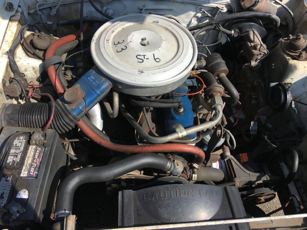
1981 Mustang Engine Information – 200 cubic inch I6 (3.3 L Ford Inline 6)
The 3.3L Ford Straight Six
The 3.3 liter, 200 ci engine was used in 1979, 1980 and 1981. However, this was not FORD’s first 200 cubic inch inline six cylinder engine. A 200 ci engine first appeared in the Mustang line in 1965 and ran through the 1970 year run. After that it was just too small to drive the monstrous 1971, 1972 and 1973 Mustangs so it was eliminated from the Mustang engine line and replaced with a bigger 250 cubic inch engine. I had a 200 cubic inch engine in a Falcon back in the 1960’s. Although it was not a fireball, it was very dependable.
Engine Basics
Year | 1981 |
Cylinders | 6 |
Displacement | 200 cu / 3.3 liters |
Power (hp) | 89 hp @ 4,200 RPM |
Torque (lb/ft) | 143 lb/ft @ 2,300 RPM |
Compression | 8.7:1 |
Bore x Stroke | 3.660 x 2.700 |
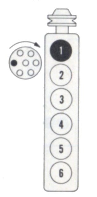
3.3L Ford V6 Firing Order
3.3 liter, 200 ci engine cylinders front to rear 1-2-3-4-5-6
Firing Order 1-5-3-6-2-4
Distributor rotation CW
More Specs
- Cylinder compression pressure: 101 PSI minimum
- Oil pressure at 2000 rpm and warm: 30-50
- Spark plugs: BSF82-C @0.050″
- Thermostat starts to open: 193-200
- Thermostat fully open: 212
- Radiator cap pressure: 16
- Cylinder head warp limit: 0.003″ per 6″: 0.006″ total
Engine & Other Torque Specifications
All torque specifications provided in this table are those recommended by FORD. If you use special bolts, follow the torque specifications provided by the manufacturer. I recommend that you use the 3 step torque technique where you torque down the bolts in three equal steps. Once you have reached the maximum recommended torque setting, go around one more time. Do not torque in a circular pattern. Always torque cross to cross.
Cylinder head bolts (3 steps) | 50-55, 60-65,70-75 |
Intake manifold nuts/bolts (4 steps) | |
Oil pump inlet tube to pump | 10-15 |
Exhaust manifold bolts | 18-24 |
Exhaust pipe to manifold bolts | |
flywheel/drive plate bolts | 75-85 |
oil pan bolts | 7-9 |
valve cover bolts | 3-5 |
Drive plate to torque converter | 30-35 |
Main bearing cap bolts | 60-70 |
Connecting rod cap nuts | 21-26 |
Fuel pump to block bolts | |
Wheel lug nuts | 80-105 |
Front hub nut | 17-25, back off 1/2 turn, then 10-15 |
Harmonic dampener | 85-100 |
Bellhousing bolts | |
Transmission to block | 28-38 |
water pump | 12-18 |
Cylinder front cover bolts | 6-9 |
Pulley to harmonic damper | 35-50 |
Rocker arm shaft to cylinder head | 30-35 |
Engine mount to block bolts | |
Engine mount to frame nuts & bolts | |
Carb to intake 2150 2V | 14-16 |
Carb to intake model 7200 VV | 12-15 |
neutral start switch C3 1979-1981 | 12-15 |
neutral start switch C4 | 6-8 |
neutral start switch AOD | 8-11 lbs |
Auto transmission pan bolts C3 | 12-17 |
Auto transmission pan bolts C4 & C5 | 12-16 |
Auto transmission pan bolts A4LD | 8-10 |
Auto transmission pan bolts AOD | 6-10 |
Spark plugs | 10-15 |
Oil pan drain Plug | 15-25 |
Engine block coolant drain plug | 5-10 |
Camshaft sprocket bolt | 35-45 |
Camshaft thrust plate to block | 12-18 |
Fuel pump to block | 12-18 |
Front cover bolts | 12-18 |
Oil filter insert to block | 10-15 |
Oil pump to block | 10-15 |
Thermostat housing bolts | 12-18 |
Fan pulley to hub | 12-18 |
fuel pump to block | 12-18 |
Valve information
Minimum valve margin width | 1/32″ |
Intake & exhaust valve seat angle | 45 degrees |
Intake & exhaust valve face angle | 44 degrees |
Intake valve seat width | 0.060-0.080″ |
exhaust valve seat width | 0.070-0.090″ |
Intake & exhaust seat runout limit | 0.002″ total |
Intake stem diameter Standard | 0.3100-.03107″ |
Intake valve stem to guide clearance | 0.0008-0.0025 |
Intake & exhaust valve face runout limit | 0.002 |
Exhaust stem diameter | 0.3098-0.3105 |
Exhaust valve stem to guide clearance | 0.0010-0.0027 |
Valve spring pressure, Intake standard | 51 – 57 @ 1.59″ |
Valve spring pressure, Exhaust standard | 142-158 @ 1.22″ |
Valve spring pressure, limit Intake & Exhaust | 10% loss |
Valve spring free length | 1.79″ |
Valve spring Installed height | 1 9/16 – 1 19/32 |
Valve lifter diameter | 0.8740-0.8754 |
Valve lifter to bore clearance Standard | 0.0007-0.0027 |
Valve lifter to bore clearance Limit | 0.005 |
Crankshaft Specifications
Connecting rod journal diameter – Standard | 2..1232-2.1240″ |
Connecting rod journal out-of-round | 0.0006″ |
Connecting rod journal taper limit | 0.0006″ per inch |
Connecting rod Bearing oil clearance desired | 0.0008-0.0015″ |
Connecting rod Bearing oil clearance allowed | 0.0008-0.0024″ |
Connecting rod side clearance std. | 0.0025-0.0105″ |
Connecting rod side clearance allowed | 0.014 |
Main Bearing journal diameter | 2.2482-2.2490″ |
Main Bearing journal out-of-round limit | 0.0006 |
Main bearing taper limit | 0.0006″ per inch |
Main Bearing journal oil clearance desired | 0.0008-0.0015″ |
Main Bearing journal oil clearance allowed | 0.0008-0.0024″ |
Crankshaft endplay | 0.004-0.008″ |
Crankshaft endplay service limit | 0.012″ |
Cylinder bore diameter | 3.6800-3.6848 |
Cylinder bore out-of round limit | 0.005″ |
Cylinder bore taper limit | 0.010″ |
Piston diameter coded red | 3.6784-3.6790 |
Piston diameter coded blue | 3.6796-3.6802 |
Piston to bore clearance | 0.0013-0.0021″ |
Piston ring end gap compression rings | 0.08-0.016 |
Piston ring end gap – oil rings | 0.015-0.055 |
Piston ring side clearance, compression rings – Standard | 0.0020-0.0040″ |
Piston ring side clearance service -limit | 0.006 |
Oil ring | Snug fit |