1967 Mustang 2100 – Series Carburetor

Ford Autolite 2100 Series Carburetor

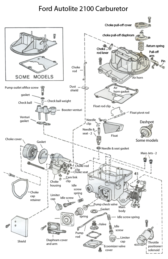
The 1967 Autolite 2100 series carburetor was used on the 289 cubic inch 2 barrel engines. It was used through 1974 across the entire Ford Lincoln and Mercury car and truck line. The carburetor was first used in 1954 so it had a life span of many years. Most small block carburetors are very similar however if you are going to the junk yard to get one, try to get one off a similar year vehicle and do not try to install a big block 2100 on a small block engine or visa-versa. Once you have your carb, generally if you purchase a quality rebuild kit you can rebuild the carb and use the specs for your year.

As the carburetor evolved, it added some nice features that made it easier to adjust and keep in tune. it also added a few different vacuum ports and anti-pollution ports. by keeping in the same year(s) as closely as possible linkages and other features should line up. It also helps when replacing your worn out carb to have it along while shopping for your new carb!

CLEANING TIPS

When cleaning this or any carburetor, it should be disassembled. Use carburetor spray cleaner and a fairly stiff bristle brush in conjunction with the solvent to remove varnish, carbon, dirt and oil. Never use wire brushes that can scratch the soft metal surfaces. They may crate an air or gas leak. Never use wire to clean out fuel or air passages as this may scratch the surfaces and introduce resistance to the flow. When clean, wash off the surfaces with a cleaner and blow out the passages with compressed air.

When installing the umbrella pump check valve, coat it with a tin layer of oil and push it into its hole to seat it.

When installing the “Idle mixture screws” screw them in until they are gently seated, then unscrew them 1 1/2 turns. This will give you a starting position for final adjustment.

When you screw in the economizer valve, do not over torque it and warp the gasket as this will cause a leak and malfunction.

When you install the choke cover, make sure the spring hoop is hooked into the tang of the choke lever or in the slot in the lever on later models.

1967 Specification Table

Year Application and Carburetor model Dry
float
level
Pump
rod
adj. **
Choke pull
down
adj.
Fast
idle cam
adj.
Auto
choke
setting
Slow
idle
speed
Fast
idle
speed
1967 289 Engine A/T w/o T.E. 31/64 C I/H 1/8 7/64 2-rich 475 1600
289 Engine A/T w/ T.E. 17/32 C O/H 1/8 7/64 2-rich 550 1600
289 Engine M/T w/o T.E. 31/64 D I/H 9/64 1/8 Index 575 1400
289 Engine M/T w/ T.E. 17/32 C I/H 1/8 7/64 Index 625 1400

* Automatic transmission in drive. ** Holes are labeled A,B,C,D on throttle linkage with “A” being closest to the throttle rod, I/H stands for inner hole.

Adjusting procedures

The following instructions should be followed in given order to properly adjust your carburetor.

Dry Float Level Adjustment –

To perform this initial adjustment, gently press the float’s metal tab to lightly seat the float needle

Cut the gauge to fit as shown in the diagram at the left. Notice that the top surface gasket is not installed.

Measure the distance from the float’s top to the bowl’s top. set the float level by adjusting the distance per the chart provided above. To adjust the float height gently bend the float’s metal tab. Be careful not to crush the needle seats rubber nose.

Pump Rod Adjustment

Position pump rod in the specified hole form the chart above. the pump lever holes are designated I/H and O/H for Inner Hole and Outer Hole.

The Throttle rod holes are designated A through D. A being the hole closest to the pivot rod and d being the hole farther from the rod.

If it is winter, and your car is sluggish, you can move the rod farther out to holes C or D. In summer, you can move the rod inward to shorten the stroke to holes B or A.

Choke Pull Down Adjustment

Bend a paper clip at a 90 degree angle 1/8 inch from one end.

Insert the paper clip into the cylinder grove and turn choke lever counterclockwise until piston is up against the clip, and will not move.

Measure the air horn gap (#3 in diagram at right) and compare the measurement against the chart above. Turn the nut marked “4” in the diagram to the right to attain proper adjustment.


1964 – 1967 Models

Manual; choke adjustment

1. With throttle valves closed. pull choke cam lever(#1 in diagram) to full choke position.

2. Measure distance as specified in chart above between wall of air horn and lower edge of choke valve #2.

3. If adjustment is needed, turn nut #3 in diagram to attain proper setting.


Diaphragm type choke pull down 1970 and up.

This step only applies to choke pull down adjustment on carburetors on 1970 and later vehicles. I have included it here because in the many years since the first mustangs, your ride may have acquired a later year carburetor. If your carburetor is not equipped with this modification, skip to the next step.

temporarily rotate thermostat cover 90 degrees rich.

1. Push down on diaphragm rod until it is seated (#1 at right)
2. Measure distance as specified in chart above between wall of air horn and lower edge of choke valve.
3. If adjustment is needed, turn nut #3 in diagram to attain proper setting._


Fast Idle cam Adjustment models 1964 and later

CHOKE VALVE PULL DOWN ADJUSTMENT must be made prior to this adjustment!
1. Temporarily turn choke cover 90 degrees rich.
2. Position index screw on index mark of fast idle cam. If adjusting a 351 Cleveland Engine, fast idle cam must be aligned with tang of intermediate cam lever.
3. Measure distance as specified in chart above between wall of air horn and lower edge of choke valve.
4. Make adjustment at point #4 as required.
5. After completion recheck and adjust auto choke setting if required.

Fast Idle cam Adjustment models 1973 & 1974

CHOKE VALVE PULL DOWN ADJUSTMENT must be made prior to this adjustment!
1. Temporarily turn choke cover 90 degrees rich. (previous step)
2. Position index screw on high step of the fast idle cam. If adjusting a 351 Cleveland Engine, fast idle cam must be aligned with tang of intermediate cam lever. (use previous diagram)
3.Place choke in pull down position by depressing choke pull down diaphragm against its stop screw. With diaphragm depressed open throttle slightly to allow the fast idle cam to fall. Close throttle and check position of fast idle cam or lever screw must contact cam at “V” mark. If not, adjust at point three.

Auto Choke setting

1. Loosen 3 choke cover screws.
2. Rotate cover and align the index mark on the choke cover with the mark specified in the specification table above. Note, you may adjust the cover 2 marks in either direction to obtain proper functionality.
3. Retighten three cover screws.

Choke over travel lever adjustment

1. Position fast idle cam “V” point in line with fast idle screw.
2. Measure distance as specified in chart above between wall of air horn and lower edge of choke valve.
3. To adjust, loosen screw and move rod up or down to obtain proper clearance. Retighten screw.

Choke un-loader adjustment

1. Hold throttle valves in wide open position.
2. Maintain a light closing pressure on choke valve.
3 Measure as specified below between upper edge of choke valve and wall of air horn.
to adjust bend tank on fast idle speed lever as required.

302 engines1/16″
197 cars all 1/4″
351 engines all 1/32″
390 engines 9/64 ”

Staged choke adjustment

Adjustment is only necessary if unit is replaced or carburetor is overhauled or choke setting is changed. Choke pull down and fast idle cam settings must be made prior to this adjustment.

1. maintain choke valve in full closed position.
2. measure air gap between forward edge of choke rod and end of slot in choke vacuum lever. Clearance must be 1/32 “.
3. if adjustment is required, hold choke rod with pliers at point indicated and rotate nylon bushing to lengthen or shorten rod as required.

Top style vent valve adjustment (you may have either this style or the side style below).

1. With throttle valve closed toward curb idle position, measure distance between lower surface of vent valve and valve seat on air horn casting. Measurement should be 7/64ths for 1967 and 5/64 for 1968 & 1969 unless specified otherwise.
2. To adjust bend vent rod in or out as needed.

Side style vent valve adjustment (you may have either this style or the top style above).

1. With slow idle speed adjusted and throttle valves closed, push in on vent valve until fully seated.
2. Measure distance seated valve and flat of vent rod. Distance should be 3/32″.
3. bend vent rod in or out as needed to obtain proper adjustment.

Dashpot adjustment

1. With throttle valves in curb idle position, depress plunger rod and measure clearance between end of rod and throttle valve lever. Clearance should be between 1/16 and 1/18 inch.
2. To adjust, loosen nut and rotate dashpot in or out as needed, then re-tighten nut.